For reference throughout the post, here's the schematic:

The potentiometer:

First, I used needle-nosed pliers to snap off the tab. I was a little bit confused by the numbering on the circuit schematic from Guitar FX. At first I went by the picture, so the wire going from the pot to the circuit board was on pin 1 in the picture above. This was wrong; so I went by the numbers on the schematic instead.
I forgot to take the pictures while I was assembling the breadboard, so I took them while I was dis-assembling them. If some of the pictures seem weird, that's my excuse.

First, I connected the ground and power on either side of the board.

I added the 100nF capacitor and some wires. It'll make more sense in the next picture.

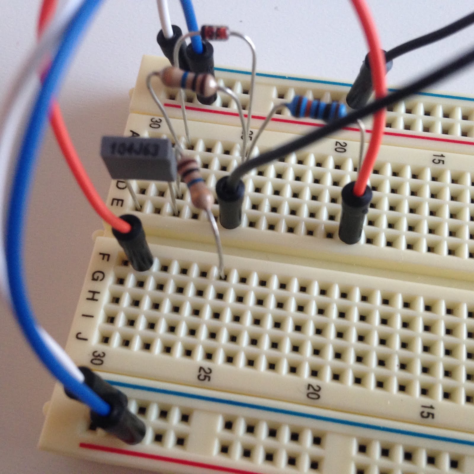
I added the zener diode and one of the 10M resistors (they are in parallel). Next, I added the 100K resistor. The two resistors and the diode in this circuit are connected to ground with the black wire. The orange wire is creating more space for the 10uF capacitor.
I added the other 10M resistor. It is not in parallel like the other 10M resistor and the diode, so I placed it going to a new row on the other side of the breadboard.

I added the 10uF capacitor and the 5.1K resistor. The 5.1K resistor connects to 9V. The 5.1K resistor and the 10uF capacitor are in parallel. The orange wire connects the capacitor back to the 100K resistor.

The whole circuit so far. The yellow and the lower orange wire are new. The yellow connects the signal from after the 100nF to the Gate of the transistor. The lower orange wire connects the 10uF capacitor and the 5.1K resistor to the Drain of the transistor.

Close-up view of the transistor. The white wire is going to pin 3 of the potentiometer.

Final view of the circuit. I added an electrolytic capacitor to the circuit. The potentiometer isn't in this picture.
Note: for some reason, I never got the electrolytic capacitors that I ordered. Luckily, I had some laying around, so I ended up using a 100uF electrolytic capacitor instead of the 47uF one that connects power to ground. Also, I used a 1uF polyfilm capacitor (the big red one) instead of the 10uF electrolytic capacitor shown in the schematic.
No comments:
Post a Comment