Now, I'm gonna test the pedal again before doing anything else.
This is similar to the previous setup, but now the circuit is on the veroboard instead of the breadboard. The jack sleeves connect to ground and the tips connect to wires leading to the input and output rows of the veroboard.
Here's a picture from the last post. To match the schematic, the input is a green wire and output is a blue wire. So the green wire connects to the tip of the input jack and the blue wire connects to the tip of the output jack. The black wire connects to the ground of the breadboard and the red wire connects to the positive 9V rail of the blackboard. The white wire here goes to pin 3 of the pot.
Now that I tested it all out on the breadboard and it worked, I have to solder the circuit together on a veroboard. I actually had a leftover piece of veroboard from my previous project, and it was a good size so I used that instead of using a new one.
It appeared rusty, I'm guessing because it was exposed to the sweat from my hands when I was trying to break it apart. To make sure it would still work, I used the (annoying) continuity function on my digital multimeter to make sure all the rows were still connected.
Bonus points if you can name that tune.
What a nice little veroboard.
I added the two holes needed for the schematic. The picture on the Guitar FX blog shows the veroboard with the copper side facing down.
I soldered the 100nF on first, although I probably should've done the two links first. The links are denoted by the black lines on the schematic.
Top view. This will correspond to the schematic.
I added the first link. My solder joints aren't really that great, but they work!
Top side view.
Added the second link.
Top side view. Sorry it's blurry.
I really thought I took more pictures throughout the process, but I got involved in the project and forgot. So here's a picture of the bottom of the veroboard. I haven't cut the leads yet because I want to make sure the circuit works. I may have to de-solder something and move it around or something, so I'll keep the leads uncut.
Top view of the circuit. As you can see, I used sockets for the transistor, diode, and electrolytic capacitor. Transistors can burn out if you solder them directly; diodes and electrolytic capacitors have polarity so I wanted to make sure I put them on the correct way.
I finished setting up the circuit on the breadboard. Now, I needed to test it to make sure I did it right. First, I wired the input/output 1/4" jacks. Mono jacks have two connections: the sleeve and the tip. Stereo jacks have three connections: the tip, the ring, and the sleeve.
Typically, a guitar pedal will have one jack of each type. The stereo jack is used as a switch to turn the battery on/off when a guitar cable is plugged in. I used one of each jack even though I'm not using a battery in the pedal at all, so really I could have used two mono jacks.
The sleeves of the jacks connect to ground. The tip is the connection that transfers the guitar signal through the effect and out the other side of the pedal to an amp. So, I soldered black wires to the sleeve of each jack and a red wire to the tip. I reinforced the joints with electrical tape.
Counting from the left, which is usually the convention, pins 1 and 2 of the potentiometer connect to ground. Pin 3 is connected to the source of the transistor. So, I put black wires on pins 1 and 2 and a white wire on pin 3. Again, I reinforced it with electrical tape.
I also soldered the DC power jack. I wanted to test as much of the pedal on breadboard as possible to make sure it all worked before I assembled it all together. The bent pin is ground and the other two pins are +9V. The reason for the third pin goes back to using a stereo jack; basically the pedal can be wired so that the battery is excluded from the circuit when the pedal is being powered with external power. Again, this is not applicable to my pedal, so I just left one of the pins empty.
First, I tested the circuit with a battery. Also, note that these jacks are two mono jacks I had from a previous project.
I also tested out the DC power jack to make sure I wired it right. This setup also has the LED connected, just for fun. The LEDs I got from Bitches Love My Switches are awesome because the resistor is already included and I don't need to worry about anything shorting out because it's all enclosed. So basically here the power flows from +9V to LED to resistor to ground.
Here is a quick video I took on my phone of me playing through the pedal on the breadboard. I'm playing a Gibson SG through a Marshall MG 100HCFX head and a MG412CF 4x12 cab. My phone fell over halfway into the video and the audio quality isn't great, but it's good to get an idea of how the pedal sounds and I'm planning on recording a new video anyway.
For reference throughout the post, here's the schematic:
The potentiometer:
First, I used needle-nosed pliers to snap off the tab. I was a little bit confused by the numbering on the circuit schematic from Guitar FX. At first I went by the picture, so the wire going from the pot to the circuit board was on pin 1 in the picture above. This was wrong; so I went by the numbers on the schematic instead.
I forgot to take the pictures while I was assembling the breadboard, so I took them while I was dis-assembling them. If some of the pictures seem weird, that's my excuse.
First, I connected the ground and power on either side of the board.
I added the 100nF capacitor and some wires. It'll make more sense in the next picture.
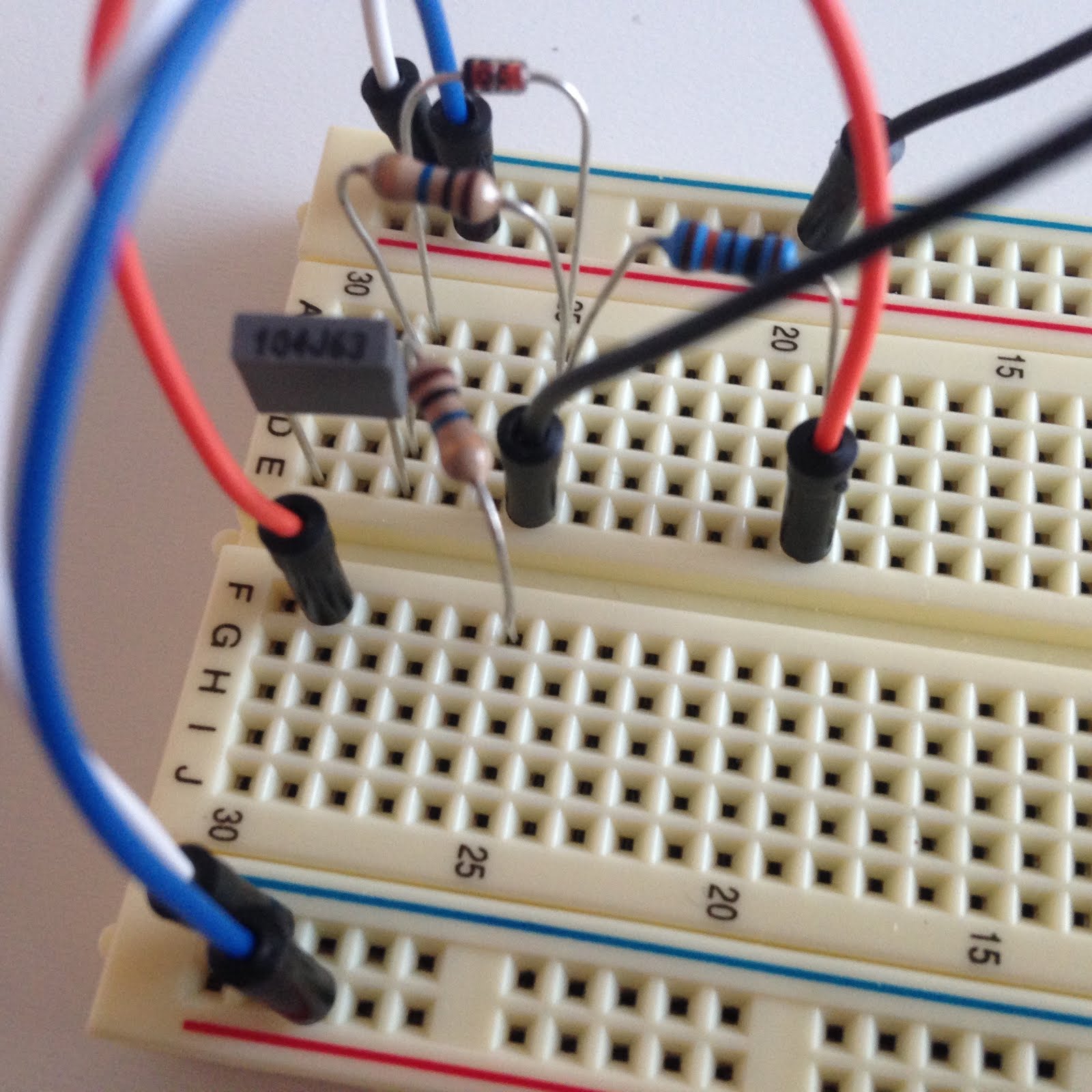
I added the zener diode and one of the 10M resistors (they are in parallel). Next, I added the 100K resistor. The two resistors and the diode in this circuit are connected to ground with the black wire. The orange wire is creating more space for the 10uF capacitor.
I added the other 10M resistor. It is not in parallel like the other 10M resistor and the diode, so I placed it going to a new row on the other side of the breadboard.
I added the 10uF capacitor and the 5.1K resistor. The 5.1K resistor connects to 9V. The 5.1K resistor and the 10uF capacitor are in parallel. The orange wire connects the capacitor back to the 100K resistor.
The whole circuit so far. The yellow and the lower orange wire are new. The yellow connects the signal from after the 100nF to the Gate of the transistor. The lower orange wire connects the 10uF capacitor and the 5.1K resistor to the Drain of the transistor.
Close-up view of the transistor. The white wire is going to pin 3 of the potentiometer.
Final view of the circuit. I added an electrolytic capacitor to the circuit. The potentiometer isn't in this picture.
Note: for some reason, I never got the electrolytic capacitors that I ordered. Luckily, I had some laying around, so I ended up using a 100uF electrolytic capacitor instead of the 47uF one that connects power to ground. Also, I used a 1uF polyfilm capacitor (the big red one) instead of the 10uF electrolytic capacitor shown in the schematic.
I didn't take pictures of all the parts this time, sorry.
My first step was to take the schematic and turn it into a circuit diagram, because I wanted to build the circuit on a breadboard before actually soldering it to a veroboard.
I used Fritzing, a free software that is mostly used to model Arduino things, I think. There's probably a better software to use, but this so happens to be the one I have.
Pretty sure this is right. Note that the transistor source is denoted by the arrow. Also wires crossing and connecting have a dot at the intersection.
Here's some resources I've been referencing while working on the pedal.
These two blogs are good to look at just to get inspired.
This guy makes a LOT of pedals and they're all really cool: Woody Laboratories
Similar thing: How Not to Make a Pedal
Forums and stuff: Free Stompboxes DIY Stompboxes Reddit DIY Pedals
You might need accounts for these sites but you can read other people's questions and ask your own and it's great. There's a community of pedal builders out there that are all really helpful.
I was unsure about the soldering iron; I read somewhere that the preferred wattage is around 20. But the one I got is a good brand and has adjustable temperature settings so it's probably fine.
Next, I needed to order stuff for this specific build. This includes an enclosure, jacks, the footswitch, and the circuit components.
I choose all of the circuit components based on the schematic from Guitar FX Layouts. There's a section in the comments where Ivlark explains which capacitors to choose:
"For all my layouts I'd tend to use multilayer ceramic for anything up to 1nF (and so for all the pF values), polyester for 1nF to 1uF and anything above 1uF I'd use electrolytic or tantalum. So for these I'd use a polyester cap for the 100nF and electrolytic or tantalums for the 10uF and 47uF. As long as they fit physically into the board, then pretty much any manufacturer will be good."
I ended up getting a 15uF tantalum capacitor instead of 10uF because Mammoth was out, but it'll probably be fine.
Everything should be delivered tomorrow, so hopefully I'll get the opportunity to build the circuit on a breadboard and test it out.
After about a year of no activity, I've decided to start up this hobby again.
This time, I'm going to try to do some things differently:
Organize BOM in Excel instead of using paper like a loser
Practice soldering way more
Prototype circuit on breadboard before soldering
Understand circuit
Put decal on pedal somehow
This time, I looked around for an easier pedal to build. The OCD had a fairly large circuit board, three pots, and a toggle switch. I think building a simpler pedal, with only one pot, will just be simpler. Plus, I'll have more room for fitting everything into the enclosure.
So, I decided on a clone of the "Super Hard-On", a pedal made by someone named Z.Vex. Apparently there are a lot of different versions of this pedal out there. It's a simple boost pedal, which adds some juice to the signal when activated and gets some nice overdrive when turned all the way up. From here on out, I'll refer to the pedal as the "SHO", because the real name is weird.
I found two blogs about building the pedal: Hot Bottles and TDPRI. I'll use them as a guide probably
Again, I'm going to be using a veroboard layout from Guitar FX Layouts.
I'm no longer at school, so I needed to buy myself a soldering station. I got an AGPtEK soldering iron along with a holder, helping hand magnifying stand, tip cleaner, and tinner from Amazon. I also got some velcro for fastening the pedal to my pedal board and some waterslide decal paper for adding a design to the pedal. We'll see how that goes. I found a website called Bitches Love My Switches, which is amazing and also has great prices on things like jacks, switches, and knobs. I got the rest of the supplies I needed for the circuit from Mammoth Electronics.


