Thursday, August 11, 2016

Done

I tried to solve my two problems and neither solution worked.

Video shows the switch popping and knob noises.


1. Fix the popping. Using this and comments on the Guitar FX thread, it seems like the standard solution for fixing popping is attaching a 1M resistor from the input jack to ground. I try this without soldering, because I was afraid of messing something up, so maybe that is why it didn't work. However, I had the resistor touching both and the signal totally cut out. I don't really know what's up with that. For now, I'm just going to ignore the popping sound.

2. The knob makes loud scratching noises when it's turned. I bought some contact cleaner and used that on the pot. It kind of worked; I think the scratching is quieter, but it's still there.

3. I think I accidentally threw out the waterslide decal paper a couple of weeks ago, so I'll guess my pedal will sport a minimalistic look for a while.

That about wraps up this project. In the future, I may write a post about how this pedal works, but I'll need to do a good amount of research for that. In the meantime, I'll probably order parts to remake the OCD in the near future.

Saturday, August 6, 2016

Put in it the Enclosure

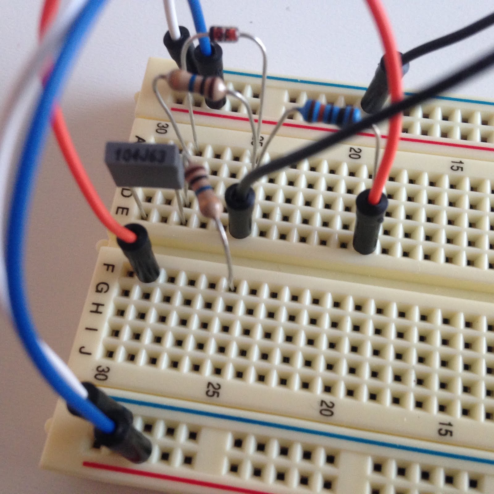
Testing with the breadboard worked! So I know I soldered everything correctly and I can move on with the build. I have all the components and everything wired up (the pot, power switch, and jacks) so now it's just a matter of putting them in the box.

Here is the schematic I used for wiring everything together in the exclosure.

I put the 1/4" jacks and the DC power jack in the enclosure. They fasten with nuts and washer, so I used pliers to tighten them up real nice like.


The footswitch used in guitar pedals are 3PDT, which means three pole double throw.

Switch Basics. The pole is how many circuits the switch can control at one time. For 3PDT, that means there are three different lug connections made at any time. The throw is the number of circuits in a pole, aka how many configurations the switch has. In state 1; lug 2 connects to lug 1, 5 to 4, and 8 to 7. In state 2; 2 connects to 3, 5 to 6, and 8 to 9. The middle row is always active; it just depends on what it connect to.

So for any guitar pedal, there is an on and an off state. In what I referred to as state 2, the pedal is off. The signal from the guitar goes through the input jack, connects from pin 9 to pin 8 of the switch, and goes through the output jack to the amp.

In state 1, the guitar input from the jack connects to the input of the board. So the guitar signal passes through the effect. Then the output from the board connects from lug 7 to lug 8, which goes through the output jack and into the amp. Through lugs 1 and 2, the LED circuit is completed so it turns on.

I put the pot and the footswitch in the enclosure, tightening them with pliers. The pot is connected to the veroboard, which can be seem to the left. There's a lot of wires around now; two ground from the pot, white from the pot to the board, input/outboard of the board, ground from the board, and power to the board. As I started soldering things, I measured and cut the wires down to make sure they would fit easily inside on the enclosure.

The 9V for everything in the pedal needs to be connected. So I twisted together the 9V wires from the DC jack, the board, and the LED. By the way, the LED I got is awesome because it's bundled together with the resistor with wires already included, so it was super easy. After I soldered these wires together, I wrapped them in electrical tape.

I did the same with the ground wires. These wires are from the DC jack, the board, both 1/4" jacks, and the three lugs of the footswitch. At this point, the only thing wired to the footswitch so far is three wires to ground on lugs 2, 3, and 6.

See? I wasn't lying to you.

I wired the ground wire from the LED to footswitch lug 1. You can see the electrical tape on the groups of 9V and ground wires and also some to separate the soldering on the board from the pot so nothing shorts out. The ground wires have been cut shorter and you can see them at the bottom of this picture.

I finished wiring the footswitch. The two green wires are on lugs 4 and 9 and they both connect to the signal (red) wire from the input jack. I twisted them, soldered them, and put electrical tape on the end in a similar fashion to the 9V and ground wire groups.
The red wire on lug 8 is the signal wire from the output jack. The middle lug (5) is the input to the effect veroboard (green wire). The blue wire on lug 7 is the output from the veroboard.

I finished it! I put the back on and screwed in the four screws.

Intense lighting!!

So sparkly.

I haven't created a demo video yet, but I did test it at this point and it worked!!! I was really excited. It has a pretty noticeable boost in the first half of the potentiometer range, but when you crank it up, this thing gets loud and fat. It's a really distorted sound and I dig it.

Two things I'm going to adjust:

1. There's a really loud pop when you turn the switch on and off. Some of my other pedals make some noise, but this one is really loud. Apparently the popping effect is magnified when the pedal is capable of more gain. To fix this, I'll add a resistor connecting the effect input to ground. More on that later.

2. The potentiometer creates a lot of scratching sounds when turning it. This is because there's dirt or dust or whenever inside the potentiometer, which is basically a needle sweeping through a range of resistance. I ordered some contact cleaner that will solve this problem.

Thursday, July 28, 2016

Test Again

Now, I'm gonna test the pedal again before doing anything else.


This is similar to the previous setup, but now the circuit is on the veroboard instead of the breadboard. The jack sleeves connect to ground and the tips connect to wires leading to the input and output rows of the veroboard.


Here's a picture from the last post. To match the schematic, the input is a green wire and output is a blue wire. So the green wire connects to the tip of the input jack and the blue wire connects to the tip of the output jack. The black wire connects to the ground of the breadboard and the red wire connects to the positive 9V rail of the blackboard. The white wire here goes to pin 3 of the pot.

Put the Circuit on Veroboard

Now that I tested it all out on the breadboard and it worked, I have to solder the circuit together on a veroboard. I actually had a leftover piece of veroboard from my previous project, and it was a good size so I used that instead of using a new one.

It appeared rusty, I'm guessing because it was exposed to the sweat from my hands when I was trying to break it apart. To make sure it would still work, I used the (annoying) continuity function on my digital multimeter to make sure all the rows were still connected.


Bonus points if you can name that tune.

What a nice little veroboard.

I added the two holes needed for the schematic. The picture on the Guitar FX blog shows the veroboard with the copper side facing down.

I soldered the 100nF on first, although I probably should've done the two links first. The links are denoted by the black lines on the schematic.

Top view. This will correspond to the schematic.

I added the first link. My solder joints aren't really that great, but they work!

Top side view.

Added the second link.

Top side view. Sorry it's blurry.


I really thought I took more pictures throughout the process, but I got involved in the project and forgot. So here's a picture of the bottom of the veroboard. I haven't cut the leads yet because I want to make sure the circuit works. I may have to de-solder something and move it around or something, so I'll keep the leads uncut.

Top view of the circuit. As you can see, I used sockets for the transistor, diode, and electrolytic capacitor. Transistors can burn out if you solder them directly; diodes and electrolytic capacitors have polarity so I wanted to make sure I put them on the correct way.

The soldering of the veroboard is complete.

Sunday, July 24, 2016

Finish Breadboard and Test It

I finished setting up the circuit on the breadboard. Now, I needed to test it to make sure I did it right. First, I wired the input/output 1/4" jacks. Mono jacks have two connections: the sleeve and the tip. Stereo jacks have three connections: the tip, the ring, and the sleeve.

Typically, a guitar pedal will have one jack of each type. The stereo jack is used as a switch to turn the battery on/off when a guitar cable is plugged in. I used one of each jack even though I'm not using a battery in the pedal at all, so really I could have used two mono jacks.


The sleeves of the jacks connect to ground. The tip is the connection that transfers the guitar signal through the effect and out the other side of the pedal to an amp. So, I soldered black wires to the sleeve of each jack and a red wire to the tip. I reinforced the joints with electrical tape.


Counting from the left, which is usually the convention, pins 1 and 2 of the potentiometer connect to ground. Pin 3 is connected to the source of the transistor. So, I put black wires on pins 1 and 2 and a white wire on pin 3. Again, I reinforced it with electrical tape.


I also soldered the DC power jack. I wanted to test as much of the pedal on breadboard as possible to make sure it all worked before I assembled it all together. The bent pin is ground and the other two pins are +9V. The reason for the third pin goes back to using a stereo jack; basically the pedal can be wired so that the battery is excluded from the circuit when the pedal is being powered with external power. Again, this is not applicable to my pedal, so I just left one of the pins empty.


First, I tested the circuit with a battery. Also, note that these jacks are two mono jacks I had from a previous project.


I also tested out the DC power jack to make sure I wired it right. This setup also has the LED connected, just for fun. The LEDs I got from Bitches Love My Switches are awesome because the resistor is already included and I don't need to worry about anything shorting out because it's all enclosed. So basically here the power flows from +9V to LED to resistor to ground.


Here is a quick video I took on my phone of me playing through the pedal on the breadboard. I'm playing a Gibson SG through a Marshall MG 100HCFX head and a MG412CF 4x12 cab. My phone fell over halfway into the video and the audio quality isn't great, but it's good to get an idea of how the pedal sounds and I'm planning on recording a new video anyway.


Thursday, July 21, 2016

Breadboard

Using this, I build the circuit on a breadboard.
For reference throughout the post, here's the schematic:


The potentiometer:
 
First, I used needle-nosed pliers to snap off the tab. I was a little bit confused by the numbering on the circuit schematic from Guitar FX. At first I went by the picture, so the wire going from the pot to the circuit board was on pin 1 in the picture above. This was wrong; so I went by the numbers on the schematic instead.

I forgot to take the pictures while I was assembling the breadboard, so I took them while I was dis-assembling them. If some of the pictures seem weird, that's my excuse.

First, I connected the ground and power on either side of the board.


I added the 100nF capacitor and some wires. It'll make more sense in the next picture.

I added the zener diode and one of the 10M resistors (they are in parallel). Next, I added the 100K resistor. The two resistors and the diode in this circuit are connected to ground with the black wire. The orange wire is creating more space for the 10uF capacitor.

I added the other 10M resistor. It is not in parallel like the other 10M resistor and the diode, so I placed it going to a new row on the other side of the breadboard.

I added the 10uF capacitor and the 5.1K resistor. The 5.1K resistor connects to 9V. The 5.1K resistor and the 10uF capacitor are in parallel. The orange wire connects the capacitor back to the 100K resistor.

The whole circuit so far. The yellow and the lower orange wire are new. The yellow connects the signal from after the 100nF to the Gate of the transistor. The lower orange wire connects the 10uF capacitor and the 5.1K resistor to the Drain of the transistor. 

Close-up view of the transistor. The white wire is going to pin 3 of the potentiometer.

Final view of the circuit. I added an electrolytic capacitor to the circuit. The potentiometer isn't in this picture.


Note: for some reason, I never got the electrolytic capacitors that I ordered. Luckily, I had some laying around, so I ended up using a 100uF electrolytic capacitor instead of the 47uF one that connects power to ground. Also, I used a 1uF polyfilm capacitor (the big red one) instead of the 10uF electrolytic capacitor shown in the schematic.

Starting the Project

I didn't take pictures of all the parts this time, sorry.

My first step was to take the schematic and turn it into a circuit diagram, because I wanted to build the circuit on a breadboard before actually soldering it to a veroboard.

I used Fritzing, a free software that is mostly used to model Arduino things, I think. There's probably a better software to use, but this so happens to be the one I have.


Pretty sure this is right. Note that the transistor source is denoted by the arrow. Also wires crossing and connecting have a dot at the intersection.

Next, I'm gonna breadboard this SOB.