Friday, July 10, 2015

Testing!!

Here is my plan for testing:

Connect the battery to the positive 9v and ground on the board, the input and output on the board to the jacks, and connect the ring of the jacks to ground.

I accomplished this using a breadboard. Also, I added the pots and toggle switch to the circuit, but forgot to take pictures. I just soldered them in place according to the schematic.

Testing the circuit at home, hooked up to my guitar and amp.

My theory for why the board isn't working is that I burned out the transistors. Also, I might be using an incorrect method to test it out? I'm not sure, this will require some more research.

Finishing Up The Board and Taking Stuff Out of the Enclosure

Okay, I ordered a new footswitch and jacks online.

I put the socket and IC on these ridiculous extenders. I wish I had done the double link in a better way so the socket could've actually fit right on top. I'm also a bit worried about how all these wires will fit inside the enclosure.

I desoldered what I had on the jacks when they were in the enclosure and added simple red and black wires: red on the tip and black on the ring.


I took all of the stuff out of the enclosure except for the LED and bezel.

In case you didn't believe me.


I Started Offboard Wiring Too Soon

I got excited and started the offboard wiring too soon. I should've stuck with the circuit board and seen it all the way through. I am full of regret.

I wasn't originally planning on testing the thing before enclosing it all up, which was extremely dumb. That planned has currently changed.

After my last post, I took off the socket spider because it is dumb.

Later, hater.


Blurry picture of something.


Added a bunch of extension wires


Bought a new socket. Big moves.


Here's what I had in the enclosure at this point.

I needed to take the pots out of the enclosure so I could connect them to the board.


Tone wire has lugs 2&3 going to ground, so I bent them with pliers and used one wire.


Gain pot has lugs 2&3 going to the same spot on the board, so I did the same.


The volume pot goes to 3 distinct locations (1&2 to different spots on the board, 3 to the 3PDT switch). I wrote down which wire was what so I wouldn't get confused later.

My next time in the lab, two wires broke off. One was the output wire on the switch, the other was one of the IC extension wires. I put that wire right back, but I had a lot of trouble fixing this wire on the switch.


It took forever to get the soldered piece of wire off of the lug.


I suck at soldering so the lug actually fell off of the switch, which I didn't know could even happen.


I got really frustrated after this, so I took a couple of days off.

Friday, July 3, 2015

Offboard Wiring

Now that the board is done, I started doing some offboard stuff.

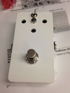
Screwed on the input jack, output jack, footswitch, toggle switch, and LED bezel. I just manually fastened them with washers and nuts.

The potentiometers had this little tab on them that I broke off using pliers.

Pot with washer and nut.

Fastened the pots in the enclosure.

The DC jack is in there too.

I kind of got caught up and didn't take too many pictures during this part. I began the necessary offboard wiring, starting with the switch and the input/output jacks. At this point, I realized that the circuit board with the stupid socket spider on top is too tall and it doesn't fit in the enclosure. I'm not sure what my solution for this is, I will probably have to take the socket off and replace it with a new one. Then I'll put the socket underneath the switch and have some wires connect it back to the board. Once I fix that, I need to connect the LED to the switch, hook up the power and ground throughout the pedal, and attach the pots to the board.

Suck it, Socket!

Warning: the post contains a lot of bullshit.

So I need to make the socket higher so it fits over the double link.

First I put the socket on a small piece of veroboard.

Added 8 links in the board.

I started to add the socket/board onto the tall links, with some difficulty. Then I realized that having the socket on veroboard connected each pin 1 to pin 5, pin 2 to pin 6, etc. That would mess up the circuit, so I ditched this idea.

I added little spider-leg links to the socket instead.

All this soldering make the left 4 pins fall off of the socket, so soldering all this crap on was difficult.

Installed the socket spider onto the board.

Now I can move on (for now). I finished putting the polyfilm capacitors on.

Back view.

Added the two ceramic capacitors.

Added the 3 electrolytic capacitors.

Set up a heat sink with an alligator clip for soldering the transistors.

Back of the finished board.

Finished board!

The board is done! All of the components are soldered on there.

Starting to Add Capacitors

After putting the resistors on the board, I stared adding capacitors.

I added the 22nF polyfilm capacitor.

At this point, I realized that the socket/IC wasn't going to fit over the double link, so I removed the double link with the intention of putting it on the other side of the board.

Added another capacitor, removed double link.