All the holes cut into my veroboard.
The next step is to solder the wire connectors that make multiple rows connected in parallel.
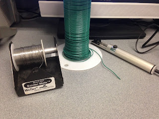
Here is my setup:
Soldering Station.
Solder, wire, and solder sucker.
Neat little holding device.

I'm not very good at it, plus one of the resistors is on the wrong side.
I put one connector on my board before I left for the day. The joint is not really as good as I would have liked, but it'll do. I want to practice some more before I move on, plus my soldering skills will build as I put components on the board.
As you can see, my board is a lot less shiny than the other day. I suspect this is due to the oil from my hands, and I'm not too worried about it.
Update 6/25: I realized I put this link on the wrong side, so I decided to fix it.
Removed the link on the wrong side by re-heating the solder.
I figured I might as well practice some more soldering.
Top: notice the solder joints are improving. They should look like little Hershey's Kisses™.
Some practice links.
Feeling more confident after practice, I re-did the first link.
Top view.
Bottom.
I added the rest of the 5 links.
Top.
Bottom. The double link really messed things up for me. I don't know if the layout I'm using is designed for a different sized veroboard, but two links were supposed to fit it one hole. That was not gonna happen, so I did this: made a link like this on the bottom of the board. Unfortunately, the socket is supposed to go over the link, so I'm gonna have to make wire extensions on top of it. It's gonna be messy.
I crossed off the links when I added them to the board so I could keep track of what was what.


No comments:
Post a Comment