Thursday, June 25, 2015

Adding Resistors

Now that the board is set up, it's time to start adding components.

Added the 18K resistor. I sort of worked my way from left to right, but also I just picked up resistors as they were.

Solder joints on first resistor.

Here's all the resistors! Looking pretty good so far.


Tuesday, June 23, 2015

Making Cuts and Wire Connections

Next, I need to make cuts in the veroboard to separate some rows into two or three smaller rows. I did this using a drill bit. I would have preferred to have an actual drill, but it worked.

All the holes cut into my veroboard.

The next step is to solder the wire connectors that make multiple rows connected in parallel.

Here is my setup:

Soldering Station.

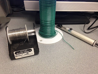
Solder, wire, and solder sucker.

Neat little holding device.

 I haven't soldered in a while, so I did some practice.

                                      
I'm not very good at it, plus one of the resistors is on the wrong side.

I put one connector on my board before I left for the day. The joint is not really as good as I would have liked, but it'll do. I want to practice some more before I move on, plus my soldering skills will build as I put components on the board.

As you can see, my board is a lot less shiny than the other day. I suspect this is due to the oil from my hands, and I'm not too worried about it.

Update 6/25: I realized I put this link on the wrong side, so I decided to fix it.

Removed the link on the wrong side by re-heating the solder.

I figured I might as well practice some more soldering.

Top: notice the solder joints are improving. They should look like little Hershey's Kisses™.

Some practice links.

Feeling more confident after practice, I re-did the first link.

Top view.

Bottom.
 I added the rest of the 5 links.
Top.

Bottom. The double link really messed things up for me. I don't know if the layout I'm using is designed for a different sized veroboard, but two links were supposed to fit it one hole. That was not gonna happen, so I did this: made a link like this on the bottom of the board. Unfortunately, the socket is supposed to go over the link, so I'm gonna have to make wire extensions on top of it. It's gonna be messy.

I crossed off the links when I added them to the board so I could keep track of what was what.

Note: it can get confusing because the two pictures on the schematic (components vs cuts and connectors) are orientated the same way even though one is a top view and one is a bottom view. You can tell the difference of the location of the cuts in some of the pictures. I just took a lot time to make sure I was putting everything in the right spot.

Saturday, June 20, 2015

Cutting Veroboard and Switching the Switch

For the actual build of this pedal, I'm using an electrical engineering lab at school that I have access to. I went there tonight to get started.

I cut the veroboard using a box cutter, it was tougher than I thought. The best method is to score and snap; I made the first cut by pretty much cutting all the way through. Took me almost 45 minutes. I finished cutting the veroboard and made it 20 x 12, leaving an extra row and extra column just in case.

All of the veroboard cut.

The 20 x 12 piece I'm using for the pedal.

Then I checked to make sure all the offboard components fit the enclosure. Turns out, the switch was way too big to fit into its designated hole. After worrying for a bit, I went over to Radio Shack and bought a SPST switch that fit perfectly. Thanks Radio Shack, too bad you're going out of business!

The next step is to make cuts and wire connections.

I'm a Big Inventory (Mayo) Fan

All my supplies arrived in the mail! It took a while, but it was worth the wait because the enclosure looks excellent. Big ups to Mammoth Electronics and Pedal Parts Plus.

I made a Wes Anderson-style video as a quick inventory:

Song: Ooh La La by The Faces

Here's an actual list of everything: (although I'm lazy so I'm not writing out all of the values; you can look at the circuit diagram)
  • enclosure
  • LED w/ bezel
  • jacks: input, output, and power
  • footswitch and toggle switch
  • 3 knobs
  • circuit elements
    • pots
    • IC
    • transistor
    • capacitors
    • resistors
    • veroboard
  • other tools: boxcutter, swiss army knife, wire, wire stripper/cutter, patience
The enclosure and veroboard are a little bit smaller than I thought they were gonna be, so I'm a little bit worried. I'm just gonna have to be very careful.

I still need to figure out how I am going to decorate the pedal: name, knob titles, etc. The pedal is powdercoated so I might want to try some sort of laserjet printed waterslide decal or something. I am going to have to do more research on the topic.